- General
-
Order number D13002 Type code CP-AM-TURNOVER Series CP Systems Categories Application module
- Description
-
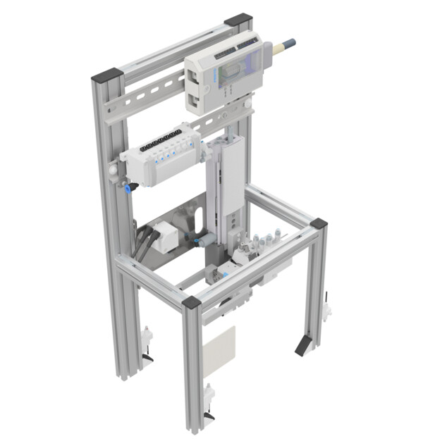
The application module Turning is designed for handling of cubic work pieces. Depending on the order specifications, workpieces are turned by means of pneumatic handling system. In order to avoid collisions when the pallets run out, the area behind the application module is monitored by means of a light barrier. A second light barrier checks the presence of the work piece on the pallet.
-
Attribute Value Electrical connection 24-pin IEEE 488 female (SysLink) Pneumatic connection Tube with 4 mm outer diameter Operating voltage 24 VDC Operating pressure 6 bar I/O 8 DI / 7 DO Z-axis Pneumatically actuated linear slider
Length: 80 mm
2 end position sensorsRevolving axis Pneumatic
0 - 210 °, continuous
Torque: 1,25 Nm
2 end position sensorsDimenions (H x W x D) 525 mm x 280 mm x 180 mm -
Application module interface (Syslink or analog terminal)
Description Reference Datatype Address
CP LabAddress
CP FactoryInputs TRUE = Lifting cylinder in upper end position +GM-BG1 Bool %I0.0 %I2.0 TRUE = Lifting cylinder in lower end position +GM-BG2 Bool %I0.1 %I2.1 TRUE = Turning cylinder at 0° +GM-BG3 Bool %I0.2 %I2.2 TRUE = Turning cylinder at 180° +GM-BG4 Bool %I0.3 %I2.3 TRUE = Gripper open +GM-BG5 Bool %I0.4 %I2.4 TRUE = Gripper closed +GM-BG6 Bool %I0.5 %I2.5 TRUE = Lifting cylinder travel blocked by pallet +GM-BG7 Bool %I0.6 %I2.6 TRUE = Work piece present +GM-BG8 Bool %I0.7 %I2.7 Outputs TRUE = Move lifting cylinder up +GM-MB1 Bool %Q0.0 %Q2.0 TRUE = Move lifting cylinder down +GM-MB2 Bool %Q0.1 %Q2.1 TRUE = Turn turning cylinder counterclockwise +GM-MB3 Bool %Q0.2 %Q2.2 TRUE = Turn turning cylinder clockwise +GM-MB4 Bool %Q0.3 %Q2.3 TRUE = Open gripper +GM-MB5 Bool %Q0.4 %Q2.4 TRUE = Close gripper +GM-MB6 Bool %Q0.5 %Q2.5 TRUE = Open lifting cylinder end position lock +GM-MB7 Bool %Q0.6 %Q2.6 -
-
-
-