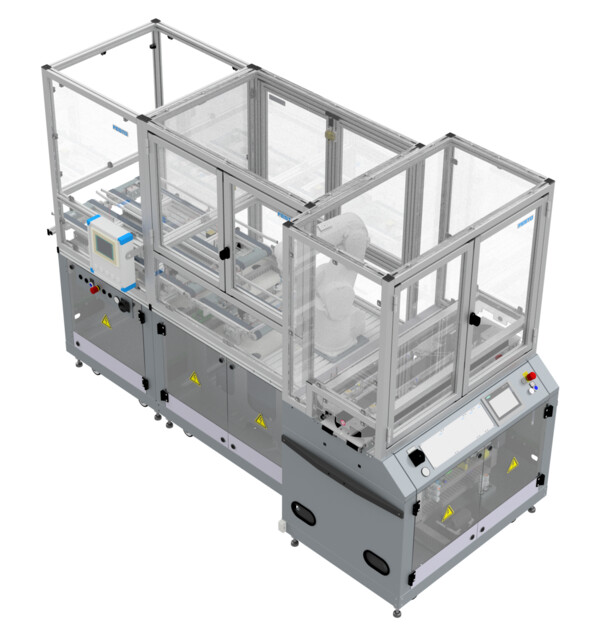
- General
-
Order number D14017 Type code CP-F-PALROB-B-C11R14 Series CP Systems Sub series CP Factory Categories Station
- Description
-
This station is designed to pick work pieces from carriers and palletize them inside a transport box or vice versa. It is joined to the carrier transport flow using an additional CP-F-BYPASS module. Transport boxes can either be fed and removed by Robotino or by hand.
-
Attribute Value Electrical connection CEE (16 A) for connecting to room infrastructure
Preconfigured modular plug for connecting to another CP Factory stationPneumatic connection Hose coupling for connecting to room infrastructure
Preconfigured modular plug for connecting to another CP Factory stationOperating voltage 230 / 400 VAC Operating pressure 6 bar Controller Siemens CPU 1512SP HMI Siemens Simatic TP700 Comfort I/O 22 DI / 18 DO (PLC)
1 DI / 2 DO (Robot controller)2x box transport belt 2x Pneumatic stopper with one end-position sensor
3x Light barrier for box detectionBox shift unit Pneumatic X-axis with two end-position sensors
2x Light barrier for box detection
RFID Read-Write-Head3x Belt drive 24 VDC motor
Bi-directional controller with slow and high speedRobot arm Mitsubishi RV-4FL
6 axis
Maximum payload: 4 kg
Maximum range: 649 mm
Repetition accuracy: +/- 0,02 mmRobot controller Mitsubishi CR750-D
Programming language: MELFA-BASIC V
Program memory: 512 programs
Position memory: 3,900 positions per programGripper Suction gripper with Venturi nozzle Festo VN-05-H-T4-PQ2-VQ2-O1-P RFID Turk BLCEN-2M12MT-2RFID-A bus node with 1 read-write-heads Other sensors Detection of pallet on carrier at work position of attached CP-F-BYPASS with light barrier
Detection of work piece on carrier at work position of attached CP-F-BYPASS with light barrierDimenions (H x W x D) 1800 mm x 800 mm x 2000 mm -
Integrated PLC
Description Reference Datatype Address Inputs TRUE = Transport box shifter at input belt +G2-BG1 Bool %I0.0 TRUE = Transport box shifter at output belt +G2-BG2 Bool %I0.1 TRUE = Transport box partially entered box shifter +G2-BG3 Bool %I0.2 TRUE = Transport box fully inside box shifter +G2-BG4 Bool %I0.3 TRUE = Pallet present on carrier at work position +G2-BG5 Bool %I0.4 TRUE = Part present on carrier at work position +G2-BG6 Bool %I0.5 FALSE = Emergency stop not acknowledged +T1-FZ1 Bool %I1.5 TRUE = Safety doors closed +K4-F2-KF1 Bool %I1.6 TRUE = Transport box detected at input belt entry +G1-BG1 Bool %I2.0 TRUE = Transport box detected at stopper at middle of input belt +G1-BG2 Bool %I2.1 TRUE = Transport box detected at stopper at exit of input belt +G1-BG3 Bool %I2.2 Only with Robotino Docking-Kit: TRUE = Coupling signal from Robotino received at input belt +G1-BG4 Bool %I2.3 TRUE = Stopper cylinder (middle of input belt) in upper end position +G1-BG5 Bool %I2.4 TRUE = Stopper cylinder (exit of input belt) in upper end position +G1-BG6 Bool %I2.5 TRUE = Transport box detected between stoppers of input belt +G1-BG7 Bool %I2.6 TRUE = Transport box detected at output belt entry +G1-BG11 Bool %I3.0 TRUE = Transport box detected at stopper at middle of output belt +G1-BG12 Bool %I3.1 TRUE = Transport box detected at stopper at exit of output belt +G1-BG13 Bool %I3.2 Only with Robotino Docking-Kit: TRUE = Coupling signal from Robotino received at output belt +G1-BG14 Bool %I3.3 TRUE = Stopper cylinder (middle of output belt) in upper end position +G1-BG15 Bool %I3.4 TRUE = Stopper cylinder (exit of output belt) in upper end position +G1-BG16 Bool %I3.5 TRUE = Transport box detected between stoppers of output belt +G1-BG17 Bool %I3.6 Outputs TRUE = Move transport box shifter to input belt +G2-MB1 Bool %Q0.0 TRUE = Move transport box shifter to output belt +G2-MB2 Bool %Q0.1 TRUE = Pull transport box onto shifter +G2-QA1:A1 Bool %Q0.4 TRUE = Push transport box out of shifter +G2-QA1:A2 Bool %Q0.5 TRUE = Drive input belt in forward direction +T1-QA1:A1 Bool %Q1.4 TRUE = Drive input belt in reverse direction +T1-QA1:A2 Bool %Q1.5 TRUE = Drive output belt in forward direction +T1-QA2:A1 Bool %Q1.6 TRUE = Drive output belt in reverse direction +T1-QA2:A2 Bool %Q1.7 TRUE = Move stopper cylinder (middle of input belt) up +G1-MB2 Bool %Q2.0 TRUE = Move stopper cylinder (middle of input belt) down +G1-MB1 Bool %Q2.1 TRUE = Move stopper cylinder (exit of input belt) up +G1-MB4 Bool %Q2.2 TRUE = Move stopper cylinder (exit of input belt) down +G1-MB3 Bool %Q2.3 Only with Robotino Docking-Kit: TRUE = Switch on coupling signal to Robotino at input belt +G1-PF1 Bool %Q2.4 TRUE = Move stopper cylinder (middle of output belt) up +G1-MB12 Bool %Q3.0 TRUE = Move stopper cylinder (middle of output belt) down +G1-MB11 Bool %Q3.1 TRUE = Move stopper cylinder (exit of output belt) up +G1-MB14 Bool %Q3.2 TRUE = Move stopper cylinder (exit of output belt) down +G1-MB13 Bool %Q3.3 Only with Robotino Docking-Kit: TRUE = Switch on coupling signal to Robotino at output belt +G1-PF11 Bool %Q3.4 Integrated robot controller
Description Reference Datatype Address Inputs TRUE = Work piece attached, vacuum created +G2-K6-BG1 Bool IN900 Outputs TRUE = Switch vacuum on +G2-K6-MB1 Bool OUT900 TRUE = Switch vacuum off +G2-K6-MB2 Bool OUT901 -
-
-
-


