- General
-
Order number D12006 Type code CP-F-RASS-C11R14 Series CP Systems Sub series CP Factory Categories Station
- Description
-
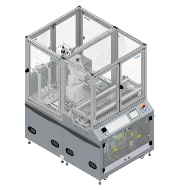
The Robot Assembly Cell is used for mounting of workpieces using a 6-axis industrial robot. The robot places the printed circuit boards into the housing and inserts fuses. A camera makes sure the work pieces are oriented correctly.
Two parallel conveyors move in opposite directions. The working position for the assembly robot is located on a third belt to avoid congestions in the material flow even during lengthy assembly processes.
-
Attribute Value Electrical connection CEE (16 A) for connecting to room infrastructure
Preconfigured modular plug for connecting to another CP Factory stationPneumatic connection Hose coupling for connecting to room infrastructure
Preconfigured modular plug for connecting to another CP Factory stationOperating voltage 230 / 400 VAC Operating pressure 6 bar Controller Siemens CPU 1512SP HMI Siemens Simatic TP700 Comfort I/O 33 DI / 17 DO (PLC)
15 DI / 5 DO (Robot controller)Box transport belt Pneumatic indexer for box
2x Light barrier for box detection
RFID read-write-head
Box orientation check with inductive sensor3x Belt drive 24 VDC motor
Bi-directional controller with slow and high speedRobot arm Mitsubishi RV-4FL
6 axis
Maximum payload: 4 kg
Maximum range: 649 mm
Repetition accuracy: +/- 0,02 mmRobot controller Mitsubishi CR750-D
Programming language: MELFA-BASIC V
Program memory: 512 programs
Position memory: 3,900 positions per programGripper changer flange Pneumatic gripper coupling
Fixed part: Zimmer-Group WWR40F-B
Loose part: Zimmer-Group WWR40L-B
Electrical signal transmission through WER02FF04 resp. WER02LF04
2x Connector for pressurized air for gripper
Detection of loose part at fixed part with inductive sensor NJR04-E2SKGripper changer storage 3x Gripper storage position with Zimmer-Group ALSR1-40-B
Gripper detection at storage position with inductive sensorsGripper 1. For PCBs: Suction gripper with Venturi nozzle Festo VN-05-H-T2-PQ1-VQ1-RO1
2. For cover parts: Parallel gripper Festo DHPS-16-A
3. For fuses: Parallel gripper Festo DHPS-10-AVision System Festo SBOC-Q-R2C
Sensor: colour sensor
Resolution: 752 x 480 pixel
Interfaces: Ethernet; CANopen
2 digital inputs / 3 digital outputs
Integrated controller: CoDeSys; IEC 61131-3
Frame rate: 150 frames/sec.
Protection class: IP65RFID 2x Turk BLCEN-2M12MT-2RFID-A bus node with 3 read-write-heads Other sensors 3x Light barrier for checking work piece orientation in the assembly bay Dimenions (H x W x D) 1800 mm x 1200 mm x 1600 mm -
Integrated PLC
Description Reference Datatype Address Inputs FALSE = Emergency stop not acknowledged +K1-F2-KF1 Bool %I0.0 TRUE = Safety doors closed +H1-F2-KF2 Bool %I0.1 TRUE = Emergency stop button pushed +S1-F2-FQ1 Bool %I0.3 TRUE = Stopper cylinder (branch) in lower end position +G1-BG20 Bool %I1.0 TRUE = Carrier detected at stopper (branch) / Stopper (branch) carrier ident code bit 0 detected +G1-BG21 Bool %I1.1 TRUE = Stopper (branch) carrier ident code bit 1 detected +G1-BG22 Bool %I1.2 TRUE = Stopper (branch) carrier ident code bit 2 detected +G1-BG23 Bool %I1.3 TRUE = Stopper (branch) carrier ident code bit 3 detected +G1-BG24 Bool %I1.4 TRUE = Carrier detected at conveyor entry (empty belt) +G1-BG26 Bool %I1.6 TRUE = Carrier detected at conveyor exit (empty belt) +G1-BG27 Bool %I1.7 TRUE = Stopper cylinder (work belt) in lower end position +G1-BG30 Bool %I2.0 TRUE = Carrier detected at stopper (work belt) / Stopper (work belt) carrier ident code bit 0 detected +G1-BG31 Bool %I2.1 TRUE = Stopper (work belt) carrier ident code bit 1 detected +G1-BG32 Bool %I2.2 TRUE = Stopper (work belt) carrier ident code bit 2 detected +G1-BG33 Bool %I2.3 TRUE = Stopper (work belt) carrier ident code bit 3 detected +G1-BG34 Bool %I2.4 TRUE = Congestion on work belt detected +G1-BG35 Bool %I2.5 TRUE = Deflector arm closed (carrier continues straight on bypass belt) +G1-BG40 Bool %I2.6 TRUE = Deflector arm opened (carrier gets diverted to work belt) +G1-BG41 Bool %I2.7 TRUE = Stopper cylinder (junction) in lower end position +G1-BG42 Bool %I3.0 TRUE = Carrier detected at stopper (junction) +G1-BG43 Bool %I3.1 TRUE = Congestion on bypass belt detected +G1-BG44 Bool %I3.2 FALSE = Junction occupied by carrier +G1-BG45 Bool %I3.3 FALSE = Pallet present on carrier at work position +G1-BG50 Bool %I3.4 FALSE = Part present on carrier at work position +G1-BG51 Bool %I3.5 TRUE = Carrier detected at conveyor entry (bypass belt) +G1-BG52 Bool %I3.6 TRUE = Carrier detected at conveyor exit (bypass belt) +G1-BG53 Bool %I3.7 FALSE = Transport box present in work position +H1-BG1 Bool %I4.0 FALSE = Transport box present in loading position +H1-BG2 Bool %I4.1 TRUE = Transport box in work position has correct orientation +H1-BG3 Bool %I4.2 TRUE = Indexing bolt 1 extended +H1-BG5 Bool %I4.4 TRUE = Indexing bolt 2 extended +H1-BG6 Bool %I4.5 TRUE = Confirmation button for box exchange pressed +H1-BG7 Bool %I4.6 Only with Robotino Docking-Kit: TRUE = Coupling signal from Robotino received +H1-KG8 Bool %I4.7 Outputs TRUE = Drive empty belt in forward direction +K1-QA1:A1 Bool %Q0.0 TRUE = Drive empty belt in reverse direction +K1-QA1:A2 Bool %Q0.1 Select empty belt speed (FALSE = normal, TRUE = slow) +K1-QA1:A3 Bool %Q0.2 TRUE = Drive bypass belt in forward direction +K1-QA2:A1 Bool %Q0.3 TRUE = Drive bypass belt in reverse direction +K1-QA2:A2 Bool %Q0.4 Select bypass belt speed (FALSE = normal, TRUE = slow) +K1-QA2:A3 Bool %Q0.5 TRUE = Drive work belt in forward direction +K1-QA3:A1 Bool %Q0.6 TRUE = Drive work belt in reverse direction +K1-QA3:A2 Bool %Q0.7 TRUE = Move stopper cylinder (branch) down +G1-MB20 Bool %Q1.0 Select work belt speed (FALSE = normal, TRUE = slow) +K1-QA3:A3 Bool %Q1.7 TRUE = Move stopper cylinder (work position) down +G1-MB30 Bool %Q2.0 TRUE = Close deflector arm (let carrier continue straight on bypass belt) +G1-MB40 Bool %Q2.6 TRUE = Open deflector arm (divert carrier to work belt) +G1-MB41 Bool %Q2.7 TRUE = Move stopper cylinder (junction) down +G1-MB42 Bool %Q3.0 TRUE = Drive transport box belt in forward direction +H1-QA4:A1 Bool %Q4.0 TRUE = Drive transport box belt in reverse direction +H1-QA4:A2 Bool %Q4.1 Select transport box belt speed (FALSE = normal, TRUE = slow) +H1-QA4:A3 Bool %Q4.2 Integrated robot controller
Description Reference Datatype Address Inputs TRUE = Part gripped +H1-BG9 Bool IN16 TRUE = Part present in assembly position +H1-BG10 Bool IN17 FALSE = Part in assembly position is upside down +H1-BG11 Bool IN18 FALSE = Part in assembly position is backwards +H1-BG12 Bool IN19 TRUE = 2 or more fuses available in tube 1 +H1-BG14 Bool IN21 TRUE = 2 or more fuses available in tube 2 +H1-BG15 Bool IN22 TRUE = 2 or more fuses available in tube 3 +H1-BG16 Bool IN23 TRUE = PCB gripper present in gripper storage +H1-BG18 Bool IN25 TRUE = Work piece gripper present in gripper storage +H1-BG19 Bool IN26 TRUE = Fuse gripper present in gripper storage +H1-BG20 Bool IN27 TRUE = Camera ready +H1-BY1:OUT0 Bool IN28 TRUE = Camera inspection passed +H1-BY1:OUT1 Bool IN29 TRUE = Camera inspection failed +H1-BY1:OUT2 Bool IN30 TRUE = Gripper opened (case gripper & fuse gripper)
TRUE = PCB attached, vacuum created (PCB suction gripper)+H1-K6-BG1
+H1-K6-BG3
+H1-K6-BG5Bool IN900 TRUE = Gripper attached to robot +H1-K6-BG6 Bool IN902 Outputs TRUE = Fasten vise +H1-MB9 Bool OUT16 TRUE = Trigger camera +H1-BY1:IN0 Bool OUT24 TRUE = Close gripper (case gripper & fuse gripper)
TRUE = Switch off vacuum (PCB suction gripper)+H1-K6-MB1 Bool OUT900 TRUE = Open gripper (case gripper & fuse gripper)
TRUE = Switch on vacuum (PCB suction gripper)+H1-K6-MB2 Bool OUT901 TRUE = Werkzeugwechsler entriegeln +H1-K6-MB3 Bool OUT902 -
-
-
-