- General
-
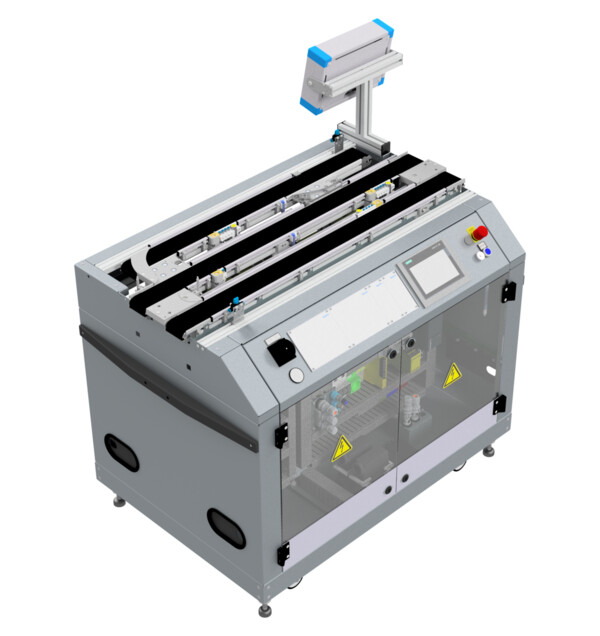
Order number D14008 Type code CP-F-BYPASS Series CP Systems Sub series CP Factory Categories Base module
- Description
-
This base module creates a linear material flow in two directions. It also provides two work positions for application modules, one of which can by bypassed. An automated junction lets carrier which don't have to go to the application module around it. That can reduce hold-ups in the material flow.
The base module Bypass comes with a PLC and all interfaces for working with any application module and MES4.
This base module is especially well souted for application modules with very long working times.
-
Attribute Value Mounting positions for application modules 2 Electrical connection CEE (16 A) for connecting to room infrastructure
Preconfigured modular plug for connecting to another CP Factory stationPneumatic connection Hose coupling for connecting to room infrastructure
Preconfigured modular plug for connecting to another CP Factory stationOperating voltage 400 VAC Operating pressure 6 bar 2x Controller Siemens CPU 1512SP
One PLC per half of the station. One of both halves encompasses the bypass belt as well as the third belt with the application module.2x HMI Siemens Simatic TP700 Comfort
One HMI panel per PLCI/O for base module 8 DI / 4 DO onboard for PLC +K1-K5-KF1
20 DI / 11 DO onboard for PLC +K3-K5-KF13x Stopper unit Pneumatic stopper cylinder with one end-position sensor
4x carrier detection & identification: inductive
RFID Read-Write-HeadBelt drive 24 VDC motor
bi-directional controller with slow and high speedRFID 2x Turk BLCEN-2M12MT-2RFID-A bus node with 3 read-write-heads Junction Pneumatic rotary cylinder with two end-position sensors Other sensors 4x carrier detection: optoelectrical
Sensors for collision avoidance when joining belt and bypassDimenions (H x W x D) 980 mm x 1200 mm x 800 mm -
Side without bypass (PLC +K1-K5-KF1)
Description Reference Datatype Address Inputs FALSE = Emergency stop not acknowledged +K1-F2-KF1 Bool %I0.0 TRUE = Stopper cylinder in lower end position +G1-BG20 Bool %I1.0 TRUE = Carrier ident code bit 0 detected +G1-BG21 Bool %I1.1 TRUE = Carrier ident code bit 1 detected +G1-BG22 Bool %I1.2 TRUE = Carrier ident code bit 2 detected +G1-BG23 Bool %I1.3 TRUE = Carrier ident code bit 3 detected +G1-BG24 Bool %I1.4 TRUE = Carrier detected at conveyor entry +G1-BG26 Bool %I1.6 TRUE = Carrier detected at conveyor exit +G1-BG27 Bool %I1.7 Outputs TRUE = Drive belt in forward direction +K1-QA1:A1 Bool %Q0.4 TRUE = Drive belt in reverse direction +K1-QA1:A2 Bool %Q0.5 Select belt speed (FALSE = normal, TRUE = slow) +K1-QA1:A3 Bool %Q0.6 TRUE = Move stopper cylinder down +G1-MB20 Bool %Q1.0 Side with bypass (PLC +K3-K5-KF1)
Description Reference Datatype Address Inputs FALSE = Emergency stop not acknowledged +K1-F2-KF1 Bool %I0.0 TRUE = Stopper cylinder (branch) in lower end position +G2-BG20 Bool %I1.0 TRUE = Carrier detected at stopper (branch) / Stopper (branch) carrier ident code bit 0 detected +G2-BG21 Bool %I1.1 TRUE = Stopper (branch) carrier ident code bit 1 detected +G2-BG22 Bool %I1.2 TRUE = Stopper (branch) carrier ident code bit 2 detected +G2-BG23 Bool %I1.3 TRUE = Stopper (branch) carrier ident code bit 3 detected +G2-BG24 Bool %I1.4 TRUE = Carrier detected at conveyor entry (bypass belt) +G2-BG26 Bool %I1.6 TRUE = Carrier detected at conveyor exit (bypass belt) +G2-BG27 Bool %I1.7 TRUE = Stopper cylinder (application belt) in lower end position +G2-BG30 Bool %I3.0 TRUE = Carrier detected at stopper (application belt) / Stopper (application belt) carrier ident code bit 0 detected +G2-BG31 Bool %I3.1 TRUE = Stopper (application belt) carrier ident code bit 1 detected +G2-BG32 Bool %I3.2 TRUE = Stopper (application belt) carrier ident code bit 2 detected +G2-BG33 Bool %I3.3 TRUE = Stopper (application belt) carrier ident code bit 3 detected +G2-BG34 Bool %I3.4 TRUE = Congestion on application belt detected +G2-BG35 Bool %I3.5 TRUE = Deflector arm closed (carrier continues straight on bypass belt) +G2-BG40 Bool %I4.0 TRUE = Deflector arm opened (carrier gets diverted to application belt) +G2-BG41 Bool %I4.1 TRUE = Stopper cylinder (junction) in lower end position +G2-BG42 Bool %I4.2 TRUE = Carrier detected at stopper (junction) +G2-BG43 Bool %I4.3 TRUE = Congestion on bypass belt detected +G2-BG44 Bool %I4.4 FALSE = Junction occupied by carrier +G2-BG45 Bool %I4.5 Outputs TRUE = Drive bypass belt in forward direction +K3-QA1:A1 Bool %Q0.0 TRUE = Drive bypass belt in reverse direction +K3-QA1:A2 Bool %Q0.1 Select bypass belt speed (FALSE = normal, TRUE = slow) +K3-QA1:A3 Bool %Q0.2 TRUE = Drive application belt in forward direction +K3-QA2:A1 Bool %Q0.3 TRUE = Drive application belt in reverse direction +K3-QA2:A2 Bool %Q0.4 Select application belt speed (FALSE = normal, TRUE = slow) +K3-QA2:A3 Bool %Q0.5 TRUE = Move stopper cylinder (branch) down +G2-MB20 Bool %Q1.0 TRUE = Move stopper cylinder (application belt) down +G2-MB30 Bool %Q3.0 TRUE = Close deflector arm (let carrier continue straight on bypass belt) +G2-MB40 Bool %Q4.0 TRUE = Open deflector arm (divert carrier to application belt) +G2-MB41 Bool %Q4.1 TRUE = Move stopper cylinder (junction) down +G2-MB42 Bool %Q4.2 -
-
-
-