Function
The Robotino is equipped with a fourth motor output and encoder input for connecting an
additional motor and encoder.
Assembly and connection
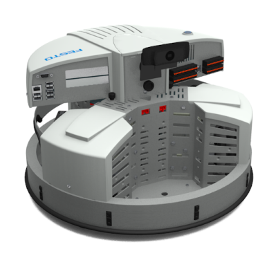
The motor output and the encoder input are mounted directly on the power electronics PCB
and can be accessed directly via the front panel of the loading bay on the Robotino.
Technology
The motor output is implemented by a four quadrant chopper (H bridge), which supplies up
to 5 A of current. The H bridge is controlled by a high-frequency PWM signal and a
direction bit. The setpoint, which is specified via the input, sets the direction bit
based on its plus or minus sign. The numeric value of the setpoint influences the PWM
signal. A setpoint of 0 does not generate any PWM signal, i.e. the H bridge does not
supply any current. A setpoint of 50 sets the high-to-low ratio within the PWM signal to
50%. A setpoint of 100 results in a continuous high signal, i.e. the H bridge supplies
maximum amperage.
The microcontroller evaluates the signal at the encoder
input (A, B channel, grey code). Rising as well as falling edges are taken into
consideration, so that the effective resolution of the encoder is four times greater
than a nominal shaft encoder resolution.