- General
-
Order number 8050101 Type code CP-L-LINEAR-C11M0 Series CP Systems Sub series CP Lab Categories Base module
- Variants
-
- Description
-
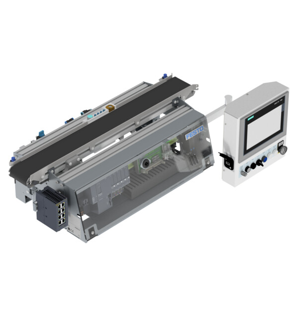
The conveyor is the main component of CP Lab and is used to transport work piece carriers to the next working position. The identification of workpieces is done via capacitive sensors at the beginning and at the end of the belt.
Every carrier is equipped with a RFID-tag on which work piece parameters are stored. A RFID read- and write-system exchanges data with the work piece that communicates through an IO-link-interface with the main controller.
The CP Lab conveyor is equipped with a PLC and all necessary interfaces in order to accomodate an application module and to communicate with MES4.
Base modules that are placed in-line can communicate through an optical 2-bit communication system.
-
Attribute Value Controller Siemens CPU 1512SP Belt drive 24 VDC motor
bi-directional controller with slow and high speedMounting positions for application modules 1 Electrical connection 4 mm banana plugs Pneumatic connection Tube with 4 mm outer diameter Operating voltage 24 VDC Operating pressure 6 bar HMI Siemens Simatic TP700 Comfort I/O for base module 8 DI / 8 DQ on board
7 DI / 2 DQ / 2 AI via IO-LinkBelt Stopper: pneumatic
4x Carrier detection & identification: inductive
2x Carrier detection: capacitive
2x Coupling sensors: optical (1x sender + 1x receiver each)RFID Siemens RF210R read/write head via IO-Link Dimenions, without HMI (H x W x D) 700 mm x 350 mm x 205 mm -
Integrated PLC
Description Reference Datatype Address Inputs TRUE = Start button pushed +P1-SF1 Bool %I1.0 FALSE = Stop button pushed (n.c.) +P1-SF2 Bool %I1.1 Control panel function switch (FALSE = F1, TRUE = F2) +P1-SF3 Bool %I1.2 TRUE = Reset button pushed +P1-SF4 Bool %I1.3 TRUE = Carrier detected at stopper position (corresponds to ident code bit 0) +G1-BG1 Bool %I1.4 FALSE = Emergency stop button pushed (n.c.) +P1-SF5 Bool %I1.5 TRUE = Carrier detected at conveyor entry +G1-BG5 Bool %I1.6 TRUE = Carrier detected at conveyor exit +G1-BG6 Bool %I1.7 TRUE = Carrier ident code bit 0 detected +G1-BG1 Bool %I42.0 TRUE = Carrier ident code bit 1 detected +G1-BG2 Bool %I42.1 TRUE = Carrier ident code bit 2 detected +G1-BG3 Bool %I42.2 TRUE = Carrier ident code bit 3 detected +G1-BG4 Bool %I42.3 Switch S1 on 'A': TRUE = Encoder A signal detected
S1 on 'R': FALSE = Coupling signal right detected+G1-KG1 / +G1-BG7 Bool %I42.4 Switch S2 on 'B': TRUE = Encoder B signal detected; S2 on 'L': FALSE = Coupling signal left detected +G1-KG2 / +G1-BG8 Bool %I42.5 TRUE = Stopper cylinder in lower end position +G1-BG9 Bool %I42.7 Control panel potentiometer 1 (0 - 10 V, 8 bit conversion) +P1-RA1 Byte %IB45 Outputs TRUE = Switch on start button signal light +P1-PF1 Bool %Q1.0 TRUE = Switch on reset button signal light +P1-PF2 Bool %Q1.1 TRUE = Switch on special function Q1 signal light +P1-PF3 Bool %Q1.2 TRUE = Switch on special function Q2 signal light +P1-PF4 Bool %Q1.3 TRUE = Drive belt in forward direction +G1-QA1-A1 Bool %Q1.4 TRUE = Drive belt in reverse direction +G1-QA1-A2 Bool %Q1.5 Select belt speed (FALSE = normal, TRUE = slow) +G1-QA1-A3 Bool %Q1.6 TRUE = Move stopper cylinder down +G1-MB1 Bool %Q1.7 TRUE = Send coupling signal left +G1-GF1 Bool %Q42.4 TRUE = Send coupling signal right +G1-GF2 Bool %Q42.5 -
-